By default, in a Kubernetes cluster with the Istio service mesh enabled, services can only be accessed inside the cluster. However, some of the services may need to be exposed to external networks as well. Kubernetes and Istio provide a variety of means to get external traffic into your cluster including NodePort, LoadBalancer, Kubernetes Ingress and Istio Gateway. With all these options, which one should be the right choice for your service mesh running in production?
I will compare all the available options, dig into the technical details, and provide a workable solution at the end of this article. Hopefully, it could be useful for your service mesh production.
Note: To better understand this article, you may need to know some Kubernetes and Istio background knowledge in advance, such as Pod, Service, NodePort, LoadBalancer, Ingress, Gateway and VirtuanlService. In case that you’re not familar with these concepts, you can still continue reading and refer to the links at the end of this article for answers when getting questions.
Access Services in the Cluster
First, let’s review how the services inside a Kubernetes cluster can be accessed.
ClusterIP
As the smallest deployment unit, Pods are dynamically created, destroyed and migrated among the minion nodes in the cluster. As a result, a pod is ephemeral and its IP changes every time after it’s recreated. Therefore, it’s difficult to access Pod directly by its IP address.
To solve this problem, Kubernetes uses Service as an abstraction for a group of backend Pods. A Service is bound to a ClusterIP, which is a virtual IP address, and no matter what happens to the backend Pods, the ClusterIP never changes, so a client can always send requests to the ClusterIP of the Service. There is a Kube-proxy which is responsible for routing client requests to a chosen backend Pod in every node.
Kube-proxy is a go application which can work in three modes:
userspace
In this mode, Kube-proxy installs iptables rules which capture traffic to a Service’s ClusterIP and redirects that traffic to Kube-proxy’s listening port. Kube-proxy then chooses a backend Pod and forwards the request to it.kube-proxy serves as an OSI layer 4 load balancer in this model. Since Kube-proxy runs in the userspace, packages need to be copied back and forth between kernelspace and userspace, adding extra latency in the proxy process. The advantage is that Kube-proxy can retry other Pod if the first Pod is not available.

iptables
To avoid the additional copies between kernelspace and userspace, Kube-proxy can work on iptables mode. Kube-proxy creates an iptables rule for each of the backend Pods in the Service. After catching the traffic sent to the ClusterIP, iptables forwards that traffic directly to one of the backend Pod using DNAT. In this mode, Kube-proxy no longer serves as the OSI layer 4 proxy. It only creates corresponding iptables rules. Without switching between kernelspace and userspace, the proxy process is more efficient.

ipvs
This model is similar to iptables because both ipvs and iptables are base on netfilter hook in kernelspace. Ipvs uses hash tables to store rules, meaning it’s faster than iptables, especially in a large cluster where there’re thousands of services. In addition, ipvs supports more load balancing algorithms.

Istio Sidecar Proxy
With service ClusterIP and Kubernetes DNS, service can be easily reached inside a cluster, however, this approach only provides very basic service discovery and limited load balancing policies. If you want more advanced features, such as flexible routing rules, more options for LB, reliable service communication, metrics collection and distributed tracing, etc., then you will need to consider Istio.
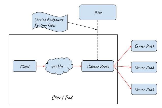
After deploying Istio in a Kubernetes cluster, Istio takes over the communication between services with sidecar proxies. The communication between services is no longer through Kube-proxy but through Istio’s sidecar proxies. The request process is like this: First, a client request is captured and redirected to the sidecar proxy by iptables. Then, the sidecar proxy chooses a backend pod according to the service discovery information and routing rules obtained from the control plane, and forwards the request to it.
Istio sidecar proxy works just like Kube-proxy userspace mode. They both work in userspace to proxy the client request and load balance among multiple back-end Pods. The difference is that Kube-proxy only works on OSI layer 4, while Istio sidecar proxy can also handle OSI layer 7 packages. So Istio sidecar proxy is much more powerful. Working with Istio control plane, the mesh of sidecar proxies can support some advanced traffic management scenarios, such as canary deployment, traffic mirroring, chaos testing(fault injection), etc.
Access Services from the Outside of a Cluster
ClusterIP is only reachable inside a Kubernetes cluster, but what if we need to access some services from outside of the cluster? Kubernetes provides the following ways to expose services to external networks.
NodePort
With NodePort, Kubernetes creates a port for a Service on the host, which allows access to the service from the node network. The Kubernetes online document only introduces the concept of NodePort, but it doesn’t explain the technical details. Let’s find out how it’s implemented using an experiment.
www.katacoda.com is an interactive learning and training platform. You can explore almost all the Kubernetes features once registered. I’ll use this website to show how NodePort is implemented under the hood. I encourage you to test it by yourself in Katacoda, it’s easy to use and totally free!
Enter this URL in your browser: https://www.katacoda.com/courses/kubernetes/networking-introduction. Katacoda will prepare a Kubernetes cluster for you, then you can connect to the Kubernetes master with a web-based interactive terminal.
Run the following command to create a NodePort type service.
kubectl apply -f nodeport.yaml
Display the created Service with the following command. We can see that webapp-nodeport-svc has been created, and Kubernetes also created a NodePort 30080 for it.
master $ kubectl get svc
NAME                   TYPE        CLUSTER-IP      EXTERNAL-IP   PORT(S)        AGE
kubernetes             ClusterIP   10.96.0.1       <none>        443/TCP        36m
webapp1-nodeport-svc   NodePort    10.103.188.73   <none>        80:30080/TCP   3m
Display the created Pods with the following command. There are two backend Pods for the service. The first one’s IP is 10.32.0.3, and the other’s is 10.32.0.5.
master $ kubectl get pod -o wide
NAME                                           READY     STATUS    RESTARTS   AGE       IPNODE      NOMINATED NODE
webapp1-nodeport-deployment-785989576b-cjc5b   1/1       Running   0          2m        10.32.0.3
webapp1-nodeport-deployment-785989576b-tpfqr   1/1       Running   0          2m        10.32.0.5
The output of netstat command shows that it’s Kube-proxy who is actually listening on 30080 port.
master $ netstat -lnp|grep 30080
tcp6      0    0    :::30080   :::*     LISTEN      7427/kube-proxy
Kube-proxy also created the corresponding iptables rules to capture traffic sending to 30080 NodePort and redirect that traffic to the two backend pods. All the iptables rules are list below, and I add comments to explain each rule’s function.
iptables-save > iptables-dump
# Generated by iptables-save v1.6.0 on Thu Mar 28 07:33:57 2019
*nat
# Chain for NodePort
:KUBE-NODEPORTS - [0:0]
# Chain for Service
:KUBE-SERVICES - [0:0]
# Chains used by both th NodePort and Service
:KUBE-SVC-J2DWGRZTH4C2LPA4 - [0:0]
:KUBE-SEP-4CGFRVESQ3AECDE7 - [0:0]
:KUBE-SEP-YLXG4RMKAICGY2B3 - [0:0]
# Capture external traffic sent to NodePort 30080 and jump to chain KUBE-SVC-J2DWGRZTH4C2LPA4.
-A KUBE-NODEPORTS -p tcp -m comment --comment "default/webapp1-nodeport-svc:" -m tcp --dport 30080 -j KUBE-SVC-J2DWGRZTH4C2LPA4
# Capture internal traffic sent to ClusterIP 10.103.188.73 and jump to chain UBE-SVC-J2DWGRZTH4C2LPA4, chain KUBE-SERVICES is responsible for handling traffic sent to Service webapp1-nodeport-svc.
-A KUBE-SERVICES -d 10.103.188.73/32 -p tcp -m comment --comment "default/webapp1-nodeport-svc: cluster IP" -m tcp --dport 80 -j KUBE-SVC-J2DWGRZTH4C2LPA4
# The first rule in chain KUBE-SVC-J2DWGRZTH4C2LPA4 sends 50% of the traffic to Pod 10.32.0.3
-A KUBE-SVC-J2DWGRZTH4C2LPA4 -m comment --comment "default/webapp1-nodeport-svc:" -m statistic --mode random --probability 0.50000000000 -j KUBE-SEP-YLXG4RMKAICGY2B3
# This rule sends the other 50% traffic to Pod 10.32.0.5
-A KUBE-SVC-J2DWGRZTH4C2LPA4 -m comment --comment "default/webapp1-nodeport-svc:" -j KUBE-SEP-4CGFRVESQ3AECDE7
# This rule forewords traffic to Pod 10.32.0.3
-A KUBE-SEP-YLXG4RMKAICGY2B3 -p tcp -m comment --comment "default/webapp1-nodeport-svc:" -m tcp -j DNAT --to-destination 10.32.0.3:80
# This rule forewords traffic to Pod 10.32.0.5
-A KUBE-SEP-4CGFRVESQ3AECDE7 -p tcp -m comment --comment "default/webapp1-nodeport-svc:" -m tcp -j DNAT --to-destination 10.32.0.5:80
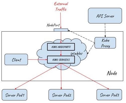
As you can see from the above experiment, if a Service is declared as NodePort type, Kube-proxy will create a port on the node and listen on that port. But Kube-proxy will not directly accept traffic from node networks, instead, it will create the corresponding iptables rules which will capture the traffic sent to the NodePort and redirect that traffic to the back-end Pods.
This diagram shows how traffic flows into a Kubernetes cluster with the help of NodePort:
LoadBalancer
NodePort is a convenient tool for testing in your local Kubernetes cluster, but it’s not suitable for production because of these limitations.
- Any node may crash or be removed from a Kubernetes cluster. When a new one comes in, the IP address of the new node is normally dynamically allocated from an address pool, which means we can’t treat node IP as a well-known IP. So it’s impractical to configure a node IP address in advance on the client side.
- A single node is a single point of failure for the system. Once the node is down, clients can’t access the cluster any more. Of course, you could mitigate risks by configuring multiple node IPs on the client side, but you will never know which one would potentially crash and when you should reconfigure these IPs.
- A single node will be the bottleneck of the system. You could also configure multiple nodes on the client side and load balance from clients, but this solution is much more problematic than server-side load balance.
A service can be declared as LoadBalancer type to create a layer 4 load balancer in front of multiple nodes. As this layer 4 load balancer is outside of the Kubernetes network, a Cloud Provider Controller is needed for its provision. This Cloud Provider Controller watches the Kubernetes master for the addition and removal of Service resources and configures a layer 4 load balancer in the cloud provider network to proxy the NodePorts on multiple Kubernetes nodes.
The below diagram shows how external traffic enters a Kubernetes cluster with the help of a load balancer. Two NodPorts are connected to the load balancer to allow external traffic to come in. There are three Pods in the cluster serving the client requests. The numbers of Nodeports and pods can be scaled out/in accordingly based on the working load of the system.
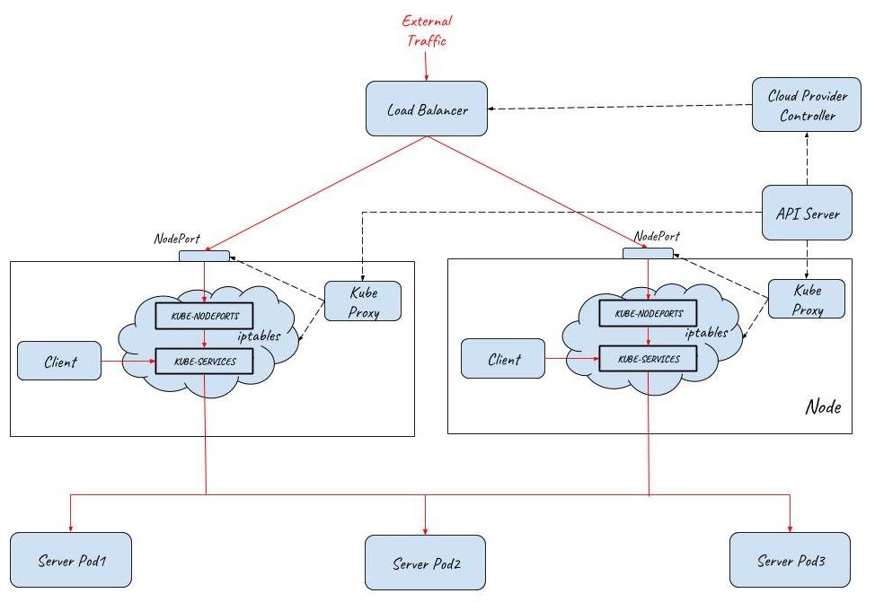
Note: A Service of LoadBalancer type is just a request to create the load balancer, the actual work is done by cloud providers, such as AWS, Azure, Amzon or Openstack. Pulic cloud provider can also associate a public IP to the created load balancer to accept traffic from the Interet.
Ingress
Kubernetes LoadBalancer works in OSI layer 4, meaning it can only dispatch inbound traffic to the backend services based on the 2-tuple of IP and Port. As a result, if we need to expose multiple services to the outside of a cluster, we must create a LoadBalancer for each service. However, creating multiple LoadBalancers can cause some problems:
- Needs more public IPs, which normally are limited resources.
- Introduces coupling between the client and the server, making it hard to adjust your backend services when business requirements change.
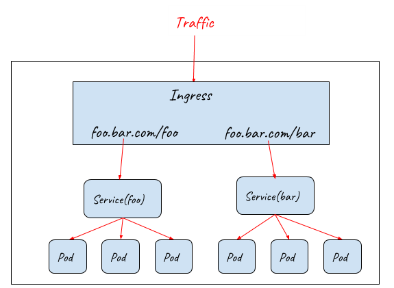
To solve these problems, Kubernetes Ingress resource is used to declare an OSI layer 7 load balancer, which can understand HTTP protocol and dispatch inbound traffic based on the HTTP URL or Host.
-
Routing requests to different backend services based on URL
-
Routing requests to different backend services based on Host
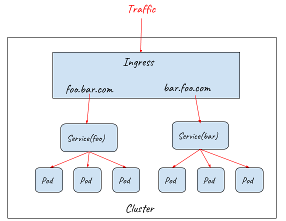
Ingress resource only defines requirements to a layer 7 load balancer such as how to route requests to backend services based on HTTP URL/Host, TLS key and certification configuration. In order for the Ingress resource to work, the cluster must have an ingress controller running. Ingress controllers configure a layer 7 proxy to fulfil the ingress rules. Most widely-used ingress controller implementations are based on some popular proxy projects including Nginx, HAProxy, Envoy, etc.
Ingress controller provides a unified entrance for the HTTP services in a cluster, but it can’t be accessed directly from outside because the ingress controller itself is also deployed as Pods inside the cluster. Ingress controller must work together with NodePort and LoadBalancer to provide the full path for the external traffic to enter the cluster.
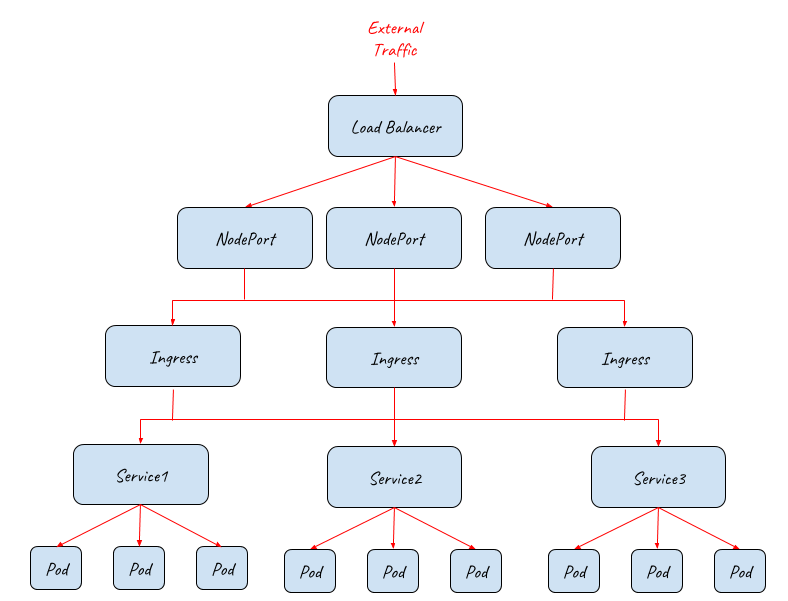
From the above diagram, we can see that the whole system is highly scalable. Each of the NodePort, Ingress or Pod layers can be scale out/in accordingly to handle different working loads.
The below diagram shows how the full entry path is implemented under the hood:
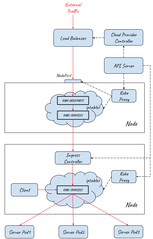
- External traffic entry path implementationInternet/External traffic reaches the layer 4 load balancer.
- Load balancer dispatches traffic to multiple NodePorts on the Kubernetes minions. This step happens in userspace.
- Traffic is captured by iptables and redirected to ingress controller Pods. This step happens in kernelspace.
- Ingress controller sends traffic to different Services according to ingress rules. This step happens in userspace.
- Finally, traffic is redirected to the backend Pods by iptables. This step happens in kernelspace.
The IP addresses of each segment in the entry path are the following: Client Request→ Load Balancer(External IP)→ Load Balancer (Node IP) → Ingress Controller Service(ClusterIP)→ Ingress Controller Pod(Pod IP)→ Backend Service(ClusterIP)→ Backend Pod(Pod IP)
How to Choose the Ingress Gateway for your Service Mesh?
Istio is doing a great job by providing a communication infrastructure layer for all the services running in the service mesh. However, until now, Istio doesn’t provide an ingress gateway solution reading for production.
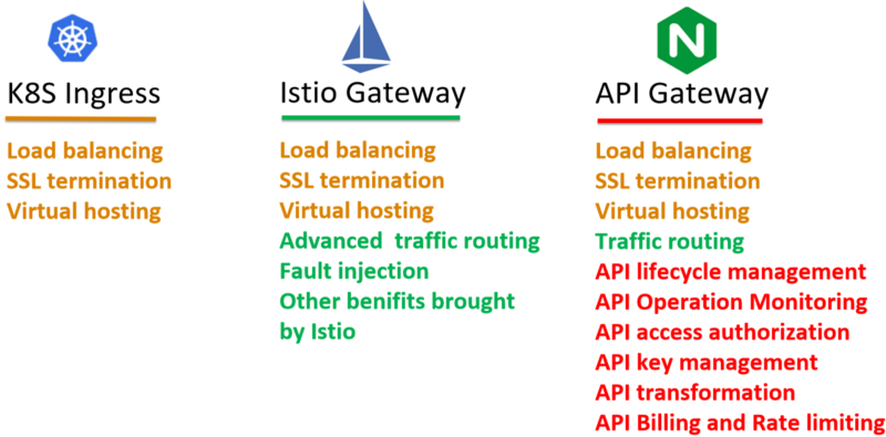
Kubernetes Ingress
Before the 0.8 release, Istio used Kubernetes Ingress resources to configure external traffic. Kubernetes Ingress provides a single entrance for external traffic, but it also has some significant shortcomings:
- Kubernetes Ingress can’t be managed by the Istio control plane. It needs to be configured with the Kubernetes Ingress rules. As a result, there are two sets of independent routing configurations in the system, one for the entrance and one for the sidecar proxies inside the mesh. The operations of the service mesh are much more complicated in this way.
- Kubernetes Ingress can only provide very basic layer 7 capabilities. It doesn’t have the same functionalities as mesh sidecars including advanced routing rules, distributed tracing, policy checking and metrics collections.
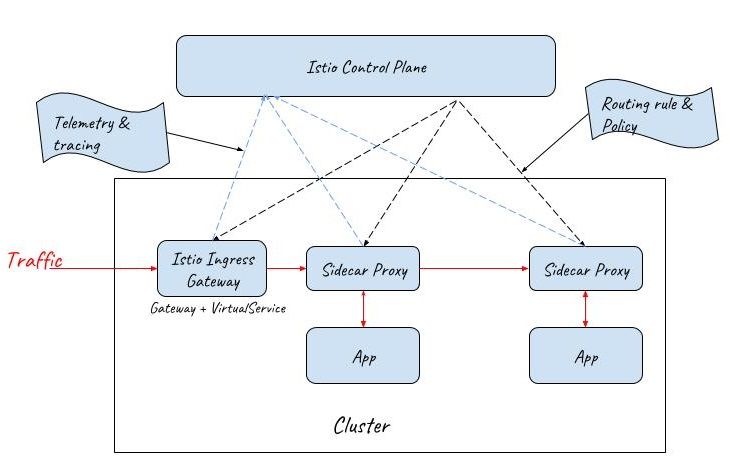
Istio Gateway
To address these concerns, Istio Gateway resource has been introduced in the 0.8 release to replace Kubernetes ingress.
Istio Gateway resource is even simpler than Kubernetes Ingress. It can only configure L4-L6 functions, such as port, host, TLS key and certification. But Gateway can be bound to an Istio VirtualService resource, which is the same resource used for routing configuration inside the mesh.
By this means, Istio can provide the same capabilities at the entrance of the mesh as inside the mesh. Both the ingress gateway and the sidecar proxies are managed by a unified mesh control plane.
API Gateway
With all the promising features provided by Istio, Istio Gateway seems like a good choice for the external traffic entrance of a service mesh. However, there is still something missing here.
A service application running in production usually has some other application-level requirements for the traffic entrance,such as:
- Authentication & Authorization for users / 3rd-party systems
- Enforce SLAs for different users / 3rd-party systems
- Data transformation / translation
- API lifecycle management
- Rate limiting
- Billing
- Other customized requirements ….
To fulfil these requirements, there’s a dozen of API Gateways on the table, including Ambassador, Kong, Traefik, Gloo, etc. All these API Gateways can be used as a Kubernetes ingress controller, but they all add some kinds of extensions to try to fill the gap between Kubernetes ingress and the reality, unfortunately, in an incompatible way. It’s a very little chance that these extensions could be standardized and included in Kubernetes Ingress or Istio Gateway in the foreseeable future. In addition to that, as far as I know, no one ingress controller officially declared supporting the integration with Istio control plane to provide Istio routing rules.
Note:
- Ambassador put Istio routing rule supporting in its roadmap https://www.getambassador.io/userguide/with-istio/
- Gloo experimentally supports Istio-based route rule discovery https://gloo.solo.io/introduction/architecture/
API Gateway + Sidecar Proxy as the External Traffic Entrance for a Service Mesh
Now let’s come back to the question thrown up at the beginning of this post: Which one is the right choice for the ingress gateway of your service mesh? Kubernetes Ingress, Istio Gateway or API Gateway? My opinion is that neither of them is capable of that by its own due to lack of some functions.
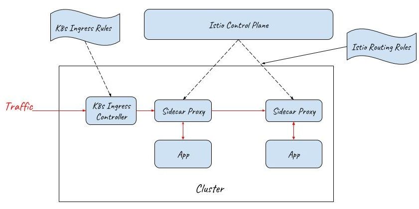
Given that it’s difficult to find an ideal out-of-box implementation which can provide both the functions of an application-layer API gateway and an Istio ingress gateway, a practical solution could be using a cascade of an API Gateway and a mesh sidecar proxy as the external traffic entrance.
As the below diagram shows, an API gateway and a sidecar proxy are used as the ingress gateway of the service mesh. Since the API Gateway already has the function of a layer 7 gateway, the sidecar proxy behind it only needs to provide the routing capability of the Istio VirtualService resource and doesn’t need to provide the capability of the Istio Gateway resource.
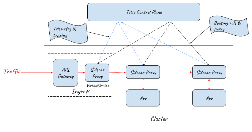
Note: NodePort and LoadBalancer should also be deployed to let external traffic in, but they are not displayed in this diagram for simplicity.
From this diagram, we can see that the sidecar proxy at the entrance is very similar to those inside the mesh. The only difference between them is that the sidecar proxy at the entrance just takes over the outbound traffic of the API Gateway, and the sidecar proxies in the mesh take over both the inbound and outbound traffic of an application pod.
Performance considerations: This approach introduces an additional hop at the mesh entrance, resulting in small more latency for client requests, but the cost is acceptable compared with the benefits.
In a service mesh, external requests have to go through a dozen of proxies and microservices to accomplish the business process, so one more proxy at the entrance shouldn’t make a significant difference. If your system is very sensitive to the latency time, I’d like to suggest you reconsider whether microservice and service mesh should be used for it. Anyway, no one architecture pattern is a silver bullet for every business scenarios.
If network throughput becomes the bottleneck, we can scale out the mesh ingress by deploying multiple API gateway and sidecar proxy combinations to handle the incoming traffic for load balancing.
Conclusion: A combination of an API gateway and a sidecar proxy could be a production-ready, full-fledged external traffic ingress for the service mesh. With this solution, we can customize and extend the API gateway to meet various application-level requirements, and leverage the flexible traffic routing, distributed tracing, metric collection and other service mesh capabilities provided by sidecar proxy. This is a production-ready ingress solution for a service mesh.
What are your thoughts on this? Let me know by leaving comments after the post.
Reference
- https://kubernetes.io/docs/concepts/services-networking/service/#virtual-ips-and-service-proxies
- https://zhaohuabing.com/2017/11/28/access-application-from-outside/
- https://medium.com/google-cloud/kubernetes-nodeport-vs-loadbalancer-vs-ingress-when-should-i-use-what-922f010849e0
- https://zhaohuabing.com/post/2018-12-27-the-obstacles-to-put-istio-into-production/#service-mesh-and-api-gateway